Jeannie Polyphonic DIY Synthesizer

the marked pin is the main current - ground is the one above.

I had similar problems and in my case it was bad soldering on one of the pins of the RECOM switch and apparently also on the coil L4.

It also seems that you did not connect the pins of the power-switch connection K5 (needs a jumper or the switch soldered).
 
Yes, you are both right, I forgot to add the jumper to K5. I will test it in a couple of hours ant post a reply if it works.
Thank you! :)
 
Hi VeNoM ,
first and befor you set power on the Jeannie Motherboard control all Parts a second time .
Checklist:
1- are the pins for the power swich shorten ?? (k5)
2-is the tantal C 9 in the right direction ??
3- Is the IC6= LT 1054 in the right direction ??
4-78L08 and 79L08 on the right place - check it double . We had it now the second time that the regulators are in the wrong place .
5- check all solder points with a glass .
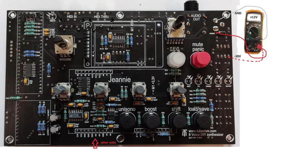
6: put the black cable from your measuring instrument on the ground
Ground is green (picture GND). you can solder a little cable on this point .
Dont forget to short the power switch , you can do it with a jumper . ( take the Jumper from the three pin Midi header )
Have you a power supply 12 V - 1 A , center positive . Can be also 12 V 0,5 ... 1,5 A.
OK , power up the jeannie with 12 V . Black cable to Ground , red cabel of your measuring instrument to the first FX 10 pin K1 connector .
You see there 3,3 3,3 ,,, GND,GND,GND,+8,+8, GND,-8,-8 direct on the PCB . This are the voltages . Example -8V can also be -7,88 V , or + 8 V can be 8,2 V...

First measure : is the 12 V there ?? This you can measure with black cable on the ground and red on the red pin of the 12 V plug.
If you have 12 V now you can measure 3,3 and +8 and - 8 V . All against ground . Means black cable on ground , red cable to 3,3 V , + 8 V and -8 Volt .
Hope this helps .
G
Andre'
 

Anhänge

  • GND.png
    GND.png
    235,3 KB · Aufrufe: 10
  • Power.png
    Power.png
    246 KB · Aufrufe: 8
Hi VeNoM ,
first and befor you set power on the Jeannie Motherboard control all Parts a second time .
Checklist:
1- are the pins for the power swich shorten ?? (k5) Yes, I've used the jumper on those two pins.
2-is the tantal C 9 in the right direction ?? I think so, if I remember correctly, I've put the shorter leg into the negative hole. Is there a way to check if I made a mistake?
3- Is the IC6= LT 1054 in the right direction ?? Yes, the point on it is pointed to the condensator next to it.
4-78L08 and 79L08 on the right place - check it double . We had it now the second time that the regulators are in the wrong place . Yes.
5- check all solder points with a glass . I don't find any bad connections.
6: put the black cable from your measuring instrument on the ground
Ground is green (picture GND). you can solder a little cable on this point .
Dont forget to short the power switch , you can do it with a jumper . ( take the Jumper from the three pin Midi header ) I did that.
Have you a power supply 12 V - 1 A , center positive . Can be also 12 V 0,5 ... 1,5 A. Power supply is 12V 1500A with center +
OK , power up the jeannie with 12 V . Black cable to Ground , red cabel of your measuring instrument to the first FX 10 pin K1 connector .
You see there 3,3 3,3 ,,, GND,GND,GND,+8,+8, GND,-8,-8 direct on the PCB . This are the voltages . Example -8V can also be -7,88 V , or + 8 V can be 8,2 V...

First measure : is the 12 V there ?? This you can measure with black cable on the ground and red on the red pin of the 12 V plug. I get 12,25V from the adapter/12V plug. Is that too much? The adapter is brand new and it is from RockPower (Warwick).
If you have 12 V now you can measure 3,3 and +8 and - 8 V . All against ground . Means black cable on ground , red cable to 3,3 V , + 8 V and -8 Volt .
Hope this helps . Some of the voltages don't add up, please se the picture bellow.
G
Andre'
Hi all,

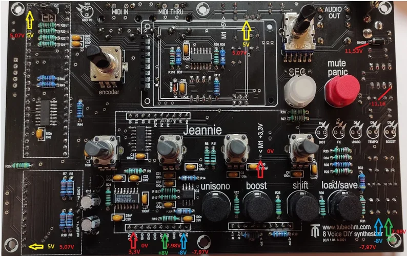
I've used the jumper from the 3 pin midi header and done the measurements, but some of the aren't right :sad:
In the picture bellow you can see which one I've got.
3V: 0 - all of them, looks like something is terribly wrong
5V: 5,07 - probably OK?
8V: 7,98 - I guess OK
-8V: -7,97 - I guess OK
12V at 1N4001 (rolfdegen's picture): 11,53 - probably not OK?
-10V next to the panic button (rolfdegen's picture): -11,16 - looks like something is terribly wrong

@andre' I've answered you questions in the quote with red

Any ideas what I did wrong?
Thank you all!

1645301739302.png
 
Hallo VeNoM

You can be happy. Very good soldering work. The voltages are OK :)
There are always small differences due to electronic component tolerances and power supplies.

M1 may have had contact problem with the probe tip.

You can now use Teensy Board and TFT Display.

Greetings Rolf
 
Zuletzt bearbeitet:
Es gibt für die Jeannie eine neue Firmware

V1.32 State Variable Filter
V1.32 Ladder Filter

Bug fixed und Änderungen:
19.02.22​
V1.31​
Filterbezeichnung korrigiert​
Probleme mit der Tastenabfrage beseitigt​
Fehler in der Grafik Engine beseitigt​
Fehler im Sequenzer mit Midi Clk beseitigt. Für Änderungen an den Parametern STEP und PITCH darf BPM nicht auf Midi stehe.​
20.02.22​
V1.32​
Oszilloskop: Trigger Verhalten und Amplituden Auflösung verbessert​
 

Anhänge

  • Firmware.zip
    2,1 MB · Aufrufe: 10
Hallo Rolf,

könntest du vllt. bei den Updatedateien auch ne Versions-Nr mit angeben. Also nicht nur "Firmware" sondern Firmware V1.xx" Man tut sich leichter beim Archivieren/Suchen.


schönen Sonntag noch...

Werner
 
Hallo VeNoM

You can be happy. Very good soldering work. The voltages are OK :)
There are always small differences due to electronic component tolerances and power supplies.

M1 may have had contact problem with the probe tip.

You can now use Teensy Board and TFT Display.

Greetings Rolf
Hi Rolf,
I've added the AD converter, the display, 6N137 and Teensy with 16GB SD card (formatted in fat32) and flashed the firmware. But the sound coming from the Jeannie doesn't sound right (I can record a sample if needed) and also the second and the 3rd potentiometer don't do anything. The sound is like it is slowed down and choppy (sounds like a fast tremolo effect is used).

This is the checklist from the manual with my answers:
1 Is the Teensy properly inserted in the socket Yes
2 the DA converter is in the right way in the socket ? Yes
3 Is K5, the plug for the mains switch short-circuited ( -jumper) ?? Yes
4 I have a 12 V power supply unit, 5.5mm /2.1 mm centre positive, minimum 1 A.
and , does voltage also come out ? Yes 1,5A, center positive, but my multimeter shows 12,25V.
5 Is the MIDI keyboard connected in MIDI IN ? Yes
6 Have I connected an audio cable with a 6.3 mm stereo jack plug? Yes, I connected my headphones in it.
7 The SD card is formatted in Fat 32 and all files have been copied to the SD card. Yes

Are you sure everything is alright, even though I got 0V from the pads where I should get 3,3V?
Thank you
 
kurze Frage an André oder Rolf:

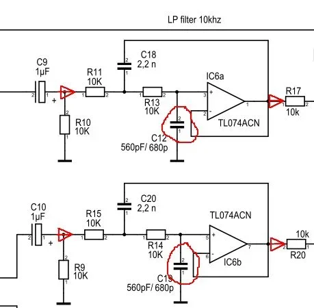
Ist es normal, dass mein Multimeter bei C12/C19 auf dem FX-Board eher einen langsam von 1.5 bis 2.0 nF ansteigenden Wert anzeigt, statt 560 oder 680 pF?
Amateurmultimeter einfach nicht genau genug?
(sind zwei blaue Kondensatoren mit "Höcker" oben wie auf dem Foto im Manual)
 
Hi Rolf,
I've added the AD converter, the display, 6N137 and Teensy with 16GB SD card (formatted in fat32) and flashed the firmware. But the sound coming from the Jeannie doesn't sound right (I can record a sample if needed) and also the second and the 3rd potentiometer don't do anything. The sound is like it is slowed down and choppy (sounds like a fast tremolo effect is used).

Which patch are you using ?

On the Filter or AMP Envelope page, all poties should work ?

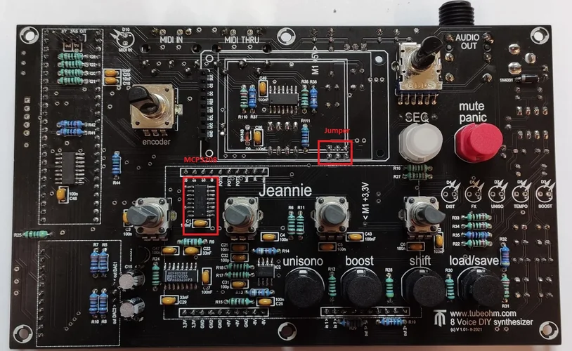
Pot query is made by IC (MCP3208). Solder again. Jumper plugged in?

Pannel PCB.png
 
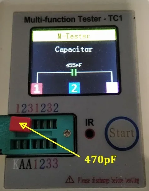
Messe die Bauteile vorher immer mit diesem Gerät
das Teil sieht praktisch aus. Wenn ich noch weitere DYI-Projekte bauen sollte, werde ich mir so einen Tester wohl auch zulegen. Mit den Messspitzen vom Multimeter ist es sowieso recht fummelig bei kleinen Bauteilen ...
 
kurze Frage an André oder Rolf:

Ist es normal, dass mein Multimeter bei C12/C19 auf dem FX-Board eher einen langsam von 1.5 bis 2.0 nF ansteigenden Wert anzeigt, statt 560 oder 680 pF?
Amateurmultimeter einfach nicht genau genug?
(sind zwei blaue Kondensatoren mit "Höcker" oben wie auf dem Foto im Manual)

Kommt natürlich auf die Bauteiltoleranzen an. Die Werte sollten im Bereich von ±20% schon stimmen. Kannst du ein Foto von den Bauteilen machen ?

Bei diesen kleinen Kondensator Werten darf das Bauteil nicht mit den Fingern berührt werden, da es sonst den angezeigten Messwert stark verfälscht.
 
Zuletzt bearbeitet:
Kannst du ein Foto von den Bauteilen machen ?
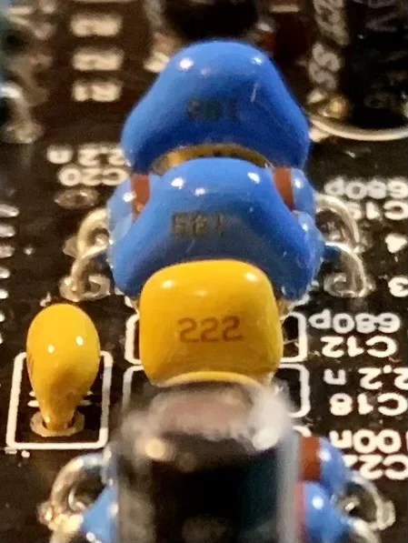
ich habe sie jetzt einfach schon mal eingelötet - hier sind sie:

IMG_E4798.JPG

Die Beschriftung ist leider (für mich) schlecht zu lesen.

Mein Multimeter ist ein einfaches Benning MM 1-3 - vielleicht verfälscht bei pF auch schon die Kapazität meiner Finger das Ergebnis? So ein Messtool wie humax5600 gezeigt hat dürfte da vermutlich besser geeignet sein.

Bevor ich da jetzt Spannung draufgebe: Sollte einer der Kondensatoren tatsächlich defekt sein - wäre ein Test schädlich, oder würde das Board dann einfach nicht funktionieren?
 
Hi Rolf,
I've added the AD converter, the display, 6N137 and Teensy with 16GB SD card (formatted in fat32) and flashed the firmware. But the sound coming from the Jeannie doesn't sound right (I can record a sample if needed) and also the second and the 3rd potentiometer don't do anything. The sound is like it is slowed down and choppy (sounds like a fast tremolo effect is used).

This is the checklist from the manual with my answers:
1 Is the Teensy properly inserted in the socket Yes
2 the DA converter is in the right way in the socket ? Yes
3 Is K5, the plug for the mains switch short-circuited ( -jumper) ?? Yes
4 I have a 12 V power supply unit, 5.5mm /2.1 mm centre positive, minimum 1 A.
and , does voltage also come out ? Yes 1,5A, center positive, but my multimeter shows 12,25V.
5 Is the MIDI keyboard connected in MIDI IN ? Yes
6 Have I connected an audio cable with a 6.3 mm stereo jack plug? Yes, I connected my headphones in it.
7 The SD card is formatted in Fat 32 and all files have been copied to the SD card. Yes

Are you sure everything is alright, even though I got 0V from the pads where I should get 3,3V?
Thank you
Hi , first , you must have 3,3 Volt. Comes from the 3,3 Vol regulator . What happens with the Coil L2 ??
The other voltages are ok . Remember , the Measure instruments had 1..3 %tolerance , all parts have 2..5 % tolerance. Means 12 V can be 12,5..12,8 or 11m5..11,8 V.
The same with the other voltages .
 
ich habe sie jetzt einfach schon mal eingelötet - hier sind sie:

Anhang anzeigen 130735

Die Beschriftung ist leider (für mich) schlecht zu lesen.

Mein Multimeter ist ein einfaches Benning MM 1-3 - vielleicht verfälscht bei pF auch schon die Kapazität meiner Finger das Ergebnis? So ein Messtool wie humax5600 gezeigt hat dürfte da vermutlich besser geeignet sein.

Bevor ich da jetzt Spannung draufgebe: Sollte einer der Kondensatoren tatsächlich defekt sein - wäre ein Test schädlich, oder würde das Board dann einfach nicht funktionieren?

Sieht doch gut aus. Mach den Strom an und lausche den Klängen. Kleines lustiges Sprichwort.. "Wer viel misst, misst Mist!" ;-) Gruß Rolf
 
Hi all,

I've used the jumper from the 3 pin midi header and done the measurements, but some of the aren't right :sad:
In the picture bellow you can see which one I've got.
3V: 0 - all of them, looks like something is terribly wrong
5V: 5,07 - probably OK?
8V: 7,98 - I guess OK
-8V: -7,97 - I guess OK
12V at 1N4001 (rolfdegen's picture): 11,53 - probably not OK?
-10V next to the panic button (rolfdegen's picture): -11,16 - looks like something is terribly wrong

@andre' I've answered you questions in the quote with red

Any ideas what I did wrong?
Thank you all!

Anhang anzeigen 130668
If M1 =0 Volt , you dont have 3,3 Volt on K1 from the FX Plug.
 
Which patch are you using ?

On the Filter or AMP Envelope page, all poties should work ?

Pot query is made by IC (MCP3208). Solder again. Jumper plugged in?

Anhang anzeigen 130734
Hi , first , you must have 3,3 Volt. Comes from the 3,3 Vol regulator . What happens with the Coil L2 ??
The other voltages are ok . Remember , the Measure instruments had 1..3 %tolerance , all parts have 2..5 % tolerance. Means 12 V can be 12,5..12,8 or 11m5..11,8 V.
The same with the other voltages .

I've managed to solve the weird sound problem. It turned out that one of the 3 legs of the 3,3V regulator was not soldered well (I bought the full kit, so it was pre-soldered). Now it sounds as it should! :)
And also I get the 3,3V reading now.
I have all 3 jumpers on and I've added solder to the MCP3208, but the 2nd and 3rd pots aren't working still... :sad:
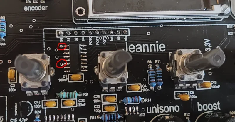
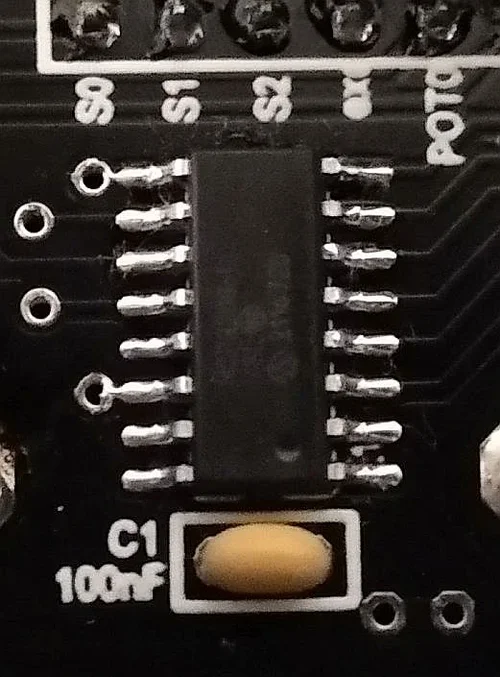
I've noticed that two legs are connected to a pad next to them. Is that OK?
1645365794842.png
 
Zuletzt bearbeitet:
I've managed to solve the weird sound problem. It turned out that one of the 3 legs of the 3,3V regulator was not soldered well (I bought the full kit, so it was pre-soldered). Now it sounds as it should! :)
And also I get the 3,3V reading now.
I have all 3 jumpers on and I've added solder to the MCP3208, but the 2nd and 3rd pots aren't working still... :sad:
I've noticed that two legs are connected to a pad next to them. Is that OK?
Anhang anzeigen 130739
Both pads are ground . This is ok .

Do the following . Press the encoder . Move it to on ADSR . Test now the 4 pots .
On the main page the pot 2 and 3 is disable .
G
Andre'
 
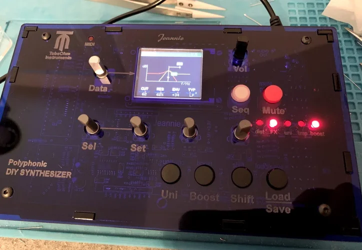
Nach der Montage des FX-Boards und dem Zusammenbau des Cases (ich musste das Kabel für den On/Off-Schalter allerdings nochmal "in situ" verlängern) erwacht sie schonmal wieder zum Leben:

IMG_4799.JPG

Heute Abend wird dann im Studio getestet, ob sie auch noch Töne (diesmal mit FX) von sich gibt. ;-)
 
Quote : I've noticed that two legs are connected to a pad next to them. Is that OK?

I would say that is ok , ´cause on my jeannie it´s the same !

C1 IC.jpg
 

Similar threads

R
Antworten
14
Aufrufe
2K
Kootsch
K


Zurück
Oben