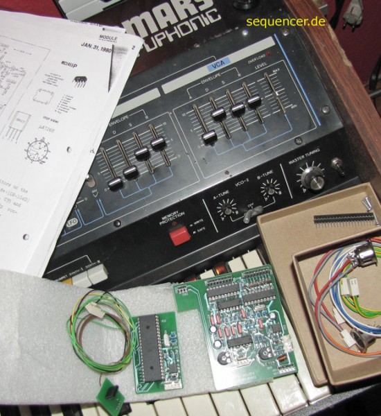
Installation guide:

1. By unscrewing 4 screws, open the Jupiter 4.

2. Drill two 15mm diameter hole for the MIDI sockets at the right edge near "Roland" script. Use a vacuum cleaner to remove the dust. This step can be done later.

3. Detach the two 8-pole connectors and the 3-pole connector from the most right green board - that is the Keyboard Assigner (see JP4SM page 20). The commectors are facing toward the keyboard at the bottom.

4. Also detach the 5-pole connector - this is where power supply feeds Key Assigner - at the top left.

5. Put the Keyboard Assigner Extension board onto the Keyboard Assigner board right at the place of the detached connectors. The Extenson board has 4 plugs that fit the original board.

6. Plug the 4 detached connectors back to the Keyboard Assigner Extension board the same positons as were originally. Be absolutely sure that the orientation of the connectors are exactly the same pin-to-pin.

7. By using a flat screwdiver gently remove the 40-pin microprocessor labeled D8048-012 from the brown motherboard.

8. Put the Patch Programmer board into the 40-pin socket. If the socket is white, you can easily find the right position and force. If the socket is blue (used on later Jupiters), you need additional rows of socket. If this is the case, first plug one row of sockets to the Patch Programmer and plug the other to the 40-pin socket. Then connect the two pieces together.

9. Plug the 2-pole MIDI IN socket into the Patch Programmer board. Notice that the 5-pin connector socket is actually a 2-pin and a 3-pin socket and one cannot be swapped with the other.

10. Plug the 3-to-2 pole interconnection cable between Patch Programmer and Keyboard Assigner Extension board. Notice that the 5-pin socket is actually divided into a 2-pin and a 3-pin socket so one can only plug the 2-pin socket to the right part.

11. Plug the 3-pole MIDI OUT socket to the Keyboard Assigner Extension board.

12. Now check if the kit is working by power on. If you have a digital multimeter you can check if the power supply is right connected before you try. To do this check short circuit between the two 6-pin ICs on the Patch Programmer and the Keyboard Assigner Extension board. Pin 5 (Ground) and 6 (+5V) should be connected.

13. The remaining connector for Control Voltages need some soldering.

control voltage association (4 pin socket on Keyboard Assigner Extension)
o o o o
| | | |
| | | | - volume -> chorus R49 or R82
| | | - cutoff -> module controller R36
| | - portamento -> key assigner PORT CONT
| - pitch bend -> control D pitch bend socket


Solder the wire labeled CUTOFF to the lower end of R36 resistance at the Module Controller board (see JP4SM page 20 and 67).

14. Solder the wire labeled VOLUME to R49 or R82 (depending on versions, see Page 49-50 in JP4SM) on the Chorus Ensemble board (see JP4SM page 20). This board is below the pitch bend holder so first remove the 4 screws that hold the pitch bend chassis. The resistance has only one end that can be reached.

15. Solder the wire labeled PORTA to the PORT CONT pad at Keyboard Assigner board. This pad is the top right soldering point of the board (top left if you look at the bottom side). See page 66 in JP4SM. On later versions the wire is directly soldered for stability while on earlier versions PORT CONT is socketed (with the TUNE knob). Best to unscrew the 4 screws the hold Key Assigner board and solder the CV wire at the bottom side.

16. Plug out the 4-pole Pitch Bend connector from Control Board D (see JP4SM page 2-3) socket labeled J2 and connect it to the small auxilary board then connect this auxilary board to J2 socket.

Now you are ready. Power on and have fun!


