Jupiter 8 Voice broken

R

roflcopta

.
einfach mal in englisch: deutsch geht natürlich auch ;-)

Its a 14bit model with groove midi interface.
When the Problem started there was only VCO1 dead, VCO2 was still working from time to time but now both are dead.
The test Program says its Voice A on the second MOD, i also swapped the boards and it turned out that the fault must be on this Board and not on the INT or MOD CON.
I did the Calibration Procedure till point 5 (VCO MOD) and those Point before were all in the tolerance and i just did some finetunning, so Power etc should be ok.
On the Voice the Noise is still Working and so do also the VCF and VCA.
When i turn the Volume really loud i fund out that i can hear the VCO1 & VCO2 as well on a very low level and they seem to work normally…
so i guess its somewhere between the VCOs and the Filter, maybe an OP?
I also did some measurements with the scope and compared them with the other working Voice (B) on the Board (and some other Voices as well), so here are the differences ive found:
TP1B: 13.764V; Squarewave
TP1A: 9.302V DC
TP2B: 13.765V; Squarewave
TP2A: 9.131V DC
i guess i could have to do with an OP(s) or maybe a CV for one (them)?

It would be glad i someone could give some advice, since i do have only basic electronic knowledge. I originally learned electrician, so i know how the electric laws, how to measure and what the parts in general do.
Thanks
kris
 
service notes mit den schemas hab ich. roland gefragt noch nicht, bieten die noch support für solche kisten?
 
Schematic hab ich (inzwischen) auch, dauert aber noch ein wenig, bis ich da durch bin.

Das Voice 1A/2A kaputt sind ist komisch, die haben keine gemeinsamen ICs.
Wenn die VCOs überhaupt noch gehen, dann müsste der Sägezahn auch noch gehen, der geht direkt aus dem VCO in den Wave-Selector.
=> guck mal, ob die VCOs wirklich laufen: IC3A-Pin 6 und IC10A-Pin6. Da sollte der Sägezahn sein, von 0 bis 10V.
 
bezüglich service manual:
es finden sich einige gratis-downloads im web, die meisten sind jedoch schlecht eingescannt und darum nur bedingt zu gebrauchen (keine seitennr. etc)...
hier der link zum einzig sauber gescannten das ich im web gefunden habe (und nebenbei noch ne gute ersatzteilbörse):
http://www.vintageplanet.nl/servicemanu ... _NOTES.pdf

zum juppi:
ich hatte glück (nun eigentlich das was ich erhofft hatte...): ein sehr erfahrener Jupiter 8 synth tech hat mir in einem anderen forum inputs zum problem geliefert.
ich werde mich da nun mal durcharbeiten und werde die resultate wieder posten.
um euch in der zwischenzeit auf dem laufenden zu halten untenstehend noch sein post:


"Ok, few questions.

Did you actually get step 5 (VCO MOD BAL) to work? If not, what was the reading at TP3?

If the noise fully works - use the VCO 1/2 mix knob to raise and lower the noise level going into the filter and it triggers only when a key is pressed, check the Waveform select ICs (IC 7 and 14) to see if all the waves are present.

IC7 - pin 11 is a square wave, pin 12 is triangle, pin 14 is saw, pin 15 is a pulse wave (all waves are 0 to 10v). Pin 13 is output of the selected wave.

IC14 is similar except 11 is noise, 12 is sine.

If you're not seeing the waveform inputs/outputs or they're not 0 to 10v, let me know what you do see. If they look good (input and output), they feed into separate BA662 ICs (IC 8 and 15) which feed into a common point at IC 24 (TL082), TP4. Let me know what you see there."
 
roflcopta schrieb:
IC7 - pin 11 is a square wave, pin 12 is triangle, pin 14 is saw, pin 15 is a pulse wave (all waves are 0 to 10v). Pin 13 is output of the selected wave.

And if there is no saw, the vco does not work. Thats the first check, than you'll know if you'll have to proceed to the left (VCO) or to the right side (Wave-Select,Filter) in the schematics.
 
ok, here is what i found:
i did step 5 (VCO MOD BAL) and TP3 is reading 0V, so that should be ok.

it seems that there is something wrong with IC7 and IC14 (TC4052BP).
here are the detailed measurements on those ICs, i also compared them with the measurements on a working Voice:
Note: all Signal Voltages are 10V if not different mentioned

PINs 1-6 are on all the ICs identical with good present waveforms on 0-10V
PINs 11-15 on the working Voice were also ok, i had the Waveforms with 0-10V as expected.
To see any Signal on the faulty ICs on PIN 11-15 i had to switch the scope from 1ms to 1us, so the signals are on much higher frequencies, the also have different Voltages, some off the with a DC offset.

IC7 (the results of the working voice are in brackets)
PIN
1. TRI
2. PWM
3. SAW
4. SQU
5. TRI
6. 0V
7. 0V
8. 0V
9. 0V
10. 15V
11. kind of a SQU 9V (SQU)
12. kind of a TRI from 4V to 7V (TRI)
13. kind of a SAW from 3V to 10V (SAW)
14. kind of a SAW from 3V to 10V (SAW)
15. PW 9V (PW)

IC14 (the Results of the working Voice are in brackets)
PIN
1. SIN
2. PW
3. PW
4. Noise
5. SAW
6. 0V
7. -5V (0V)
8. 0V
9. 12V
10. 0V
11. Noise
12. kind of a SIN 2V (SIN)
13. kind of a SQU 9V (PW)
14. kind of a SAW 11V (SAW)
15. kind of a SQU 9V (PW)
16 11V (15V)

According to the Datasheet of the IC7/IC14 (TC40552BP) the Y-side seems to be ok, while the X-side is faulty.
on IC14 i also have different Voltages on PIN7 (-5V) and PIN 16 (11V) compared to a working Voice.
any advice?


edit: i did some measurements on the OSC outputs (IC3A Pin6 and IC11A Pin 6) and they show me both a SAW with 12V which is only visible if i switch the scope from 1ms to 1us (compared to a working voice with a 10V SAW on the normal frequency range), so it seems that the fault must be somewhere there...

danke für den tip, fetz
 
1µs is 1MHz - which means you won't hear anything. Much to high frequency, about highest frequency this oscillator can do at all - just from the op-amp and comparator.
=> CV of VCO not ok or exponentiator (CA3046) gone.

More when I'm back home...
 
Herr Fliegel von Roland (Norderstedt) wiegelt alles ab, was Vintage Reparaturen angeht.
Sein Argument: Keine Teile mehr :sad:
Ich habe es in den letzten 3 Jahren 4 x versucht. System700, Jupiter8, VP330 und 184 Keyboard. Hat er alles nicht mehr angenommen.
 
und weiter gehts, mit mehr input vom anderen tech in amerika:


quoting is going to get messy, so I'll address parts at a time.

I agree 1-6 (X side) looks good. Pins 6 and 8 are tied to ground on both ICs. Pin 7 is tied to ground on IC7, but tied to -5v on IC14, so those readings look fine. Pin 16 (Vdd) on IC14 is shown as +10v and on IC7 is shown as the standard arrow with no voltage mark which seems to map to +15v.

Pins 9 and 10 are your waveform select pins, so you should see the binary codes 00, 01, 10, 11 show up (0v and +10 or more) on those 2 pins as you cycle the front panel waveform selectors.

For sanity sake, check the keyboard CV coming into the board. You can probe on the connector (IM pins 1, 3, 5, 7 - cv A1, A2, B1, B2) or at the ICs (4558's): IC1a (6 in, 7 out), 9a (2 in, 3 out), 1b (6 in, 7 out), 9b (2 in, 1 out). That dumps into the CA3046's (IC2 for vco1, IC10 for vco2). The output of the 3046 (pin 8) goes into the TL080's (IC3 and IC11) which is essentially the master waveform generator. If the sawtooth coming out of IC3/11 is not a clean 0->10v then the problem is likely in one of those ICs (IC1/2/3, 9/10/11).

Although - I have a memory of getting a JP-8 in that had a problem like this. When I took the voice board out, I could see where a tech before me had tried replacing those ICs and the problem was still there. Turned out to be one of the transistors in that part of the circuit (TR1 or TR2) but I can't find my notes on that particular repair to say which transistor it was.


darauf meine antwort:
how can it be that the X-Side works fine and the Y-Side not? looks somehow strange to me, since i have all the expected Waveforms on the X-Side of IC7/IC14 (so they are somewhere generated as they should) but not on the Y-Side and on the OSC out??


edit: X-Side ist natürlich Voice B... :oops:
 
Kann Dir leider nicht helfen. Wenn Du einen Techniker brauchst, der sich den Jupiter mal ansieht, schick mir eine PM.
 
alright, here we go:
- Waveform select works on IC7/14 Pin 9/10: i can see the binary codes
- Keyboard CV is ok (A1, A2, B1, B2 on IM 1, 3, 5, 7)
- Out on IC 1A/9A Pin7 is ok
- Out on IC 3/11 Pin 6 is not ok
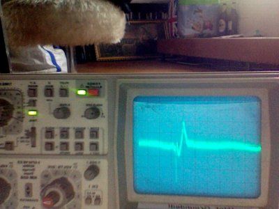
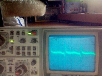
so i had a closer look on the input of IC 2/10 Pin 9 and found some periodic glitches in the CV.
Pictures 1 shows IC10 Pin9 with 20mV/2us
Picture 2 Shows the same with 20mV/1us
They CV is moving according to Keyboard but i guess those HF Glitches are causing the problems.
IC2 was fine this time, but i remeber that ive seen kind of the same sometimes
the other working voices do have normal DC CV (on IC2/10 Pin 9)
so the problems seems to be between IC 1A/9A and IC2/10
 

Anhänge

  • Picture2.jpg
    Picture2.jpg
    88,3 KB · Aufrufe: 31
  • Picture1.jpg
    Picture1.jpg
    85,6 KB · Aufrufe: 31
update from old synthguy:

Well, IC2 and IC10 are shared between the voices on the card. IC2 (pins 6,7,8 and 9,10,11) is Voice A VCO1, pins 1,2,3 and 3,4,5 is Voice B VCO1. Same division of labor for IC10.

CV comes into pin 9 (Voice A) and pin 2(Voice B). Pins 6 and 4 are tied to ground. Pins 7,10 and 3 are the emitters and 8,11 and 5,1 are the collectors.

Pins 1 and 11 are tied back to the emitters via TR1 and IC1 (VCO1) and TR7 and IC9 (VCO2). Pins 8 and 5 are the "outputs" that drive the waveform.

You can compare and contrast the 2 voices and two VCOs per voice to see if you can find any commonality into what is working and what isn't. At that point there should be a single component causing the problem since it is across multiple oscillators. I'd probably blow off addtional testing and take a chance at this point and just replace the RC4558, CA3046, and maybe the TL080 if I was really reaching, especially if it was a customer machine. I can unsolder and resolder components fast with good tools and it would save some time on the repair clock.


Zurück
Oben